How Mechanical Design, Manufacturing & Automation Supports CNC Programming
Mechanical Design, Manufacturing & Automation aids CNC programming by giving the information each program requires. The shape, size, and materials are all planned ahead of time. Process planning picks the machine, its parts, its tools, and the order in which the cuts are made. Programmers turn these options into G-code, and before the metal is cut, simulations check the code. Then, the machine is linked to loading, probing, and inspection by automation. This makes sure that the results are always the same. Coders don't have to fix as many problems that could have been avoided when one stage feeds into the next. This book is for people who are in charge of training, plants, departments, or want to learn more about that chain and the skills that go with it.
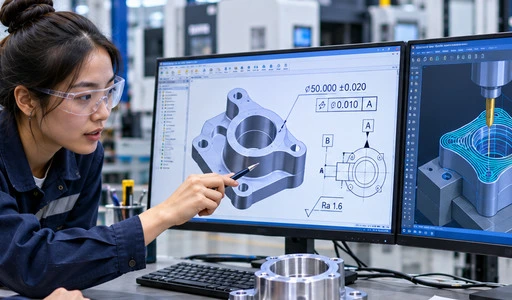
How Mechanical Design Influences CNC Programming?
Drawings, Datums, and Tolerances Set the Starting Point
CNC programmers read the drawing first, then start the software. The part's width, height, thread callouts, surface finish, and material notes tell you what tools and setups it needs. The ASME Y14.5-2018 document explains geometric dimensioning and tolerancing. A clear datum scheme gives the programr a single point of reference to use when figuring out how to move work around. A programr has to guess when a value or range is not clear or easy to reach. If you guess, you'll lose. If the bore is tight, you might need to make an extra finishing pass. If the bore is loose, you won't have to. These changes depend on how much you can handle. I tell new students to make a list of the important parts of their program first, and then build their program around those.
Part Features That Raise Machining Difficulty
Some parts of programs and setups make them longer and harder to use. Long tools that can bend are needed to get into deep pockets. Cutting force can make walls that aren't very strong shake. If there are undercuts or small inside radii, you might need different cutters or more layouts. With each setup, there is a new chance for position error and a shift in the work. A design for manufacturability (DFM) review finds these issues right away. An engineer can sometimes make a hole bigger or rounder so that a normal end mill can go through it. Few small changes have been made to the program to make it easier to use and speed it up. If you want to find problems with how tools are used that a model might miss, you should have programmers review the design.
Revision Control Protects the Program
Plans are changed for almost all projects; even small changes make a big difference. When a hole is moved by one millimeter, the inspection plan, the toolpath, and the places where the fixtures will go all change. If an old file is used for programming, the shop makes the wrong part. On the shop floor, only files that have been released are used. Each program has a list of the drawing revisions it was made for. Tracking changes can also help a team figure out where a bug came from. It's easy to do this on training projects, and it will save them time when they get to the real plant.
How Manufacturing Process Planning Turns Design Intent into CNC Instructions?
Choosing the Right Process and Machine
Make a plan for how the part will be made. To decide which turning, milling, drilling, boring, and other methods to use, the planner looks at the shape, the material, the tolerances, the surface finish, and other things. A lathe needs a shaft that has grooves in it. It is possible for your milling machine or machining center to work with a housing that has shapes and holes in it. It's also important how big the batch is, since a long setup can only work if it's broken up into many pieces. Textbooks on making things, like Groover's Fundamentals of Modern Manufacturing, explain process selection as a balance between form, substance, and amount. Machine selection includes the number of axes, the size of the work area, and the power of the spindle. It is clear to the programr what they need to do in a good plan.
Fixtures, Clamping, and Positioning
Holding the work in place makes sure it is safe and correct. Pick a datum surface, keep the part in place, and clamp it with enough force to stop cutting loads without bending it. This will help you make a good plan. If you clamp down on parts with thin walls too hard, they can bend before the first cut is made. The frame also tells the work where to start, so the programr needs to know exactly where zero is. When a clamp gets in the way of a toolpath, they have to change the order of cuts or add a setup. First I show them how to set up a simple vise. Then they make their own fixtures. If you want to learn faster, watch a clamp crash in a simulation instead of listening to a teacher talk.
Materials, Tools, and Cutting Parameters
It changes a lot of numbers in a program. Ti-316 and other steels like it make more heat and wear down tools more quickly. Steel, on the other hand, is easy to cut. The planner then sets the depth of cut, the speed of the spindle, and the rate of feed. It also picks the shape, material, and coating of the tool. The author of the book mechanical design, manufacturing & automation, Altintas, talks about how these options change cutting forces and machine vibration. Things that don't work right can cause chatter and rough surfaces. What you do when you enter and leave the tool is also important. A smooth motion leaves fewer marks on the finished surface. They also cut down on moves that don't do anything because air cutting takes time and doesn't add any value. On a short process sheet, the owner, operator, and inspector can all see the same plan.
How CNC Programming and Simulation Convert Requirements into Machine Operations?
From CAD and CAM to G-Code
A list of tools, the stock, and how the work is held are all set by the programmers. After that, the toolpaths are either made in CAM software or by hand. One more step takes the toolpaths and turns them into code for each controller. The program format and address words that G-code and M-code use are different, but they are all based on ISO 6983-1. That's why a program made for one controller might not work with another without being changed. G-codes tell machines how to move and cut in a circle or a straight line. On the other hand, M-codes tell things to do, like turning on the spindle, adding coolant, and changing tools. Sets link the show to the real world. If one link breaks, the machine will cut in the wrong spot.
Toolpath Strategy Shapes Time, Wear, and Finish
Two programs can make the same part, but they can do very different things with it. Passes that pocket and contour shape the final walls, and adaptive roughing keeps the tool steady in place. There are thread milling, drilling, and finishing passes that can be used on different parts. Smid's CNC Programming Handbook talks about pre-set cycles and ways to fix typing mistakes that make programs shorter. With tool radius compensation, the programr can fix cutters that are worn out without having to start over with the path. When you turn, the program is longer and less clear depending on whether you use roughing cycles or profile commands. It's not enough to just focus on one number. You should also think about cycle time, tool life, and surface quality.
Simulation and First-Article Checks
With simulation, the code can be tested on a fake machine before it is run on the real one. It can warn you about running into fixtures, going too far, making too many cuts or too few cuts, and having too much or too little stock. Also, it can guess how long the cutting will take. When the operator runs the first part in single-block mode, they check the offsets and then measure the key dimensions. You use the plan or process sheet to fill in any blanks between the part and the plan. If you crash an expensive machine or piece of material, you may have to shut it down for repairs. This order is very important. For new people, simulations are also a safe way to train and learn from their mistakes.
How Manufacturing Automation Extends CNC Programming Capability
From Single Machine to Coordinated Cell
When a machine is automated, it joins a production cell because it can work on its own. Robots, pallet changers, conveyors, and vision systems do the work and move parts. They also load and unload goods. Machine signals, safety interlocks, and how the robot and machine talk to each other are all controlled by PLCs. Safety planning should be a part of every cell project because ISO 12100 gives general rules for figuring out how dangerous machinery is to build. This is how you need to set up the CNC program. When it's done, it needs to leave the door and fixture in a known state for the next cycle and let you know it did so. Someone who knows how cells work writes code that works with the robot instead of against it.
Probing and Inspection Close the Loop
Probes and gages take measurements that are sent back to the process. Touch probes can find where a part is, tell you how far away the work needs to be, or check a feature on a part before it leaves the machine. With coordinate measuring machines and vision systems, you can see trends like tool wear, fixture error, or thermal drift. People who are using the machine or the computer can change the tool's offset when a value being measured gets close to its limit. This is done to keep the parts from moving out of range. In order for this feedback to work, the programs must correctly use variables and offsets. Being good at programming directly aids quality control. You can store and use these kinds of values in a simple way with macro variables, which we talk about in class.
Where Automation Pays Off, and What to Weigh
When you need to do the same thing over and over, like inspecting, sorting, and palletizing, automation is the best way to go. Less handling can be done so that the spindle can be used more often, but it costs money and engineers' time. People who are buying something should think about how much it will cost them to get it set up, keep it running, train people on how to use it, test it for safety, and make any necessary changes to the products in the future. Some of the things that show if a cell works well are downtime, cycle time, overall equipment effectiveness (OEE), and first-pass yield. That number can be raised more easily when programs are stable and have been shown to work. Schools and plants should learn how to program and process first, since an automated cell will only do what it is told to do.
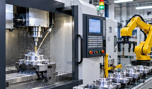
How E.C.R Academy Builds These Skills in Learners
A Full-Process Curriculum
The steps in E.C.R Academy's Mechanical Design, Manufacturing & Automation course that are taken are part drawing analysis, process programming, simulation verification, and machining. Students learn how to read drawings, choose the right positioning and clamping tools, decide if a material can be machined, and plan the steps that need to be taken in a certain order. Writing programs for milling (for flat surfaces and holes), drilling, boring, and tapping is part of their job. They also write programs for turning (for outside surfaces and inside holes). Macro variables can be used in parametric programs for surfaces that are complicated. You will also learn about coordinate systems, G-codes, and M-codes in this class. In every module, safety at work is talked about, and green manufacturing ideas are taught, like how to use machines that use less energy. This course is for people who work with process planning, CNC programming, running machines, and making sure the quality is good.
Labs, Simulation, and Project-Based Delivery
There are four training labs that go along with the course. These are a CNC turning lab, a CNC milling lab, a machining center lab, for digital manufacturing. In the turning lab, CNC lathes and software that makes turning look real are both used together. In the milling lab, extra parts and measuring tools are added to milling machines and simulation software. There are three-axis machining centers, multi-axis simulation software, and offline programming workstations in the machining center lab. These help make parts that are made in more than one process and automatically change tools. The digital manufacturing lab has licensed CAM software, fast computers, and systems for checking simulations. There is a standard way to teach that is based on projects and combines theory and practice. Starters get diagrams, animated demos, small-group lessons, and computer practice before they touch a real machine.
Faculty, Certificates, and Partners
A group of college teachers and business engineers teach the course, and skilled master trainers help students with technical issues and give them career advice. Because it's online, you can study when you're not in lab. Learners who meet the requirements may be able to get certificates in CNC turning and milling. It's a good idea to start your career at a company that makes general and specialized tools, cars and planes, CNC tools or cutting tools. Since 2010, E.C.R. Almost 500,000 people in China and 28 other countries have been trained and tested by it. It is known that more than 300,000 of these students have earned skills certifications. We're working with over 500 companies to help them. Businesses, schools, and industry groups are some of our clients.
Conclusion
Some choices are made that change how the CNC is programd before the machine starts up. Metrics, tolerances, and other parts of a part that make it hard to cut are set by its mechanical design, manufacturing & automation. Process planning picks the method, machine, fixtures, tools, and parameters for cutting. Those choices are turned into controller code by programming. Before the code is used in real life, it is tested in simulations and first-article checks to make sure it works. Automation adds handling, probing, and inspection that make results repeatable, but it only does what the program tells it to do, which means you need to know how to code and how to run a business. There are rules about how drawings should look, how codes should be written, and how safe they should be in standards like ASME Y14.5, ISO 6983-1, and ISO 12100. They are ready for every link in the chain when they go through training that includes everything, from analyzing drawings to running simulations to cutting metal.
FAQ
1. What background should learners have before joining the course?
You should be able to read part drawings, draw simple machines, know basic metals and how to work with them, and know how to use a computer. People who aren't very good at learning can get some basic help before they start the main modules.
2. Can beginners without CNC programming experience study this course?
Yes. The theory modules go from easy to hard topics with the help of diagrams and moving examples. As you go through the steps of programming, you will go over commands, see how they work in a case, and practice. Before they do real machining, students learn in small groups and use simulations to get better.
3. Which careers does the course support?
It helps companies that make special and general equipment, as well as companies that make cars, planes, CNC tools, and cutting tools. Some of their jobs are to set up processes, program CNC machines, do precise machining, and make sure the work is done well.
4. Why should programmers learn simulation?
Before the real machining starts, simulation checks the toolpaths for collisions, overcuts, and undercuts and tries to guess how long the machining will take. That keeps the machines, tools, and workpieces safe while the students work on them.
Talk to E.C.R Academy About Mechanical Design, Manufacturing & Automation Training
For classes in mechanical design, manufacturing & automation, E.C.R. Businesses, schools, and industry groups are welcome at Academy. As part of our course, our teachers, engineers, and master mentors teach us how to do simulations, draw diagrams, process program, and machine parts. Email ecr2008@enteredu.com with your training goals, how many people you want to train, and when you want to do it. You can go to enteredu.com to learn more. We'll help you choose a good plan.
References
1. ASME, Y14.5 Dimensioning and Tolerancing, 2018
2. ISO, ISO 6983-1 Automation Systems and Integration: Numerical Control of Machines, Program Format and Definitions of Address Words, 2009
3. ISO, ISO 12100 Safety of Machinery: General Principles for Design, Risk Assessment and Risk Reduction, 2010
4. Groover, M. P., Fundamentals of Modern Manufacturing, Wiley, 2020
5. Altintas, Y., Manufacturing Automation: Metal Cutting Mechanics, Machine Tool Vibrations, and CNC Design, Cambridge University Press, 2012
6. Smid, P., CNC Programming Handbook, Industrial Press, 2007